

Sewer and drainage · Works network · DN 30–300
3D sewer inspection for works networks in Vienna, Lower Austria and Burgenland
In a works network the main run is rarely the problem – the topology is: which discharge hangs on which section, which branch is missing from the as-built plan, which pipe has ended blind since a conversion. The multi-turn steerable camera head turns into the side connections and records where it travels; from this the pipe network route is rendered digitally. Afterwards the coherence of the network is documented, instead of having to be pieced together from plan fragments and the memory of the last conversion. We drive out from Traiskirchen – a short journey and prompt appointments instead of long distances. Report the section on +43 (0) 2252 53169 or in writing to office@cft.at, and we will settle manhole access, nominal diameter and when driving on the site is possible.

What we do on site
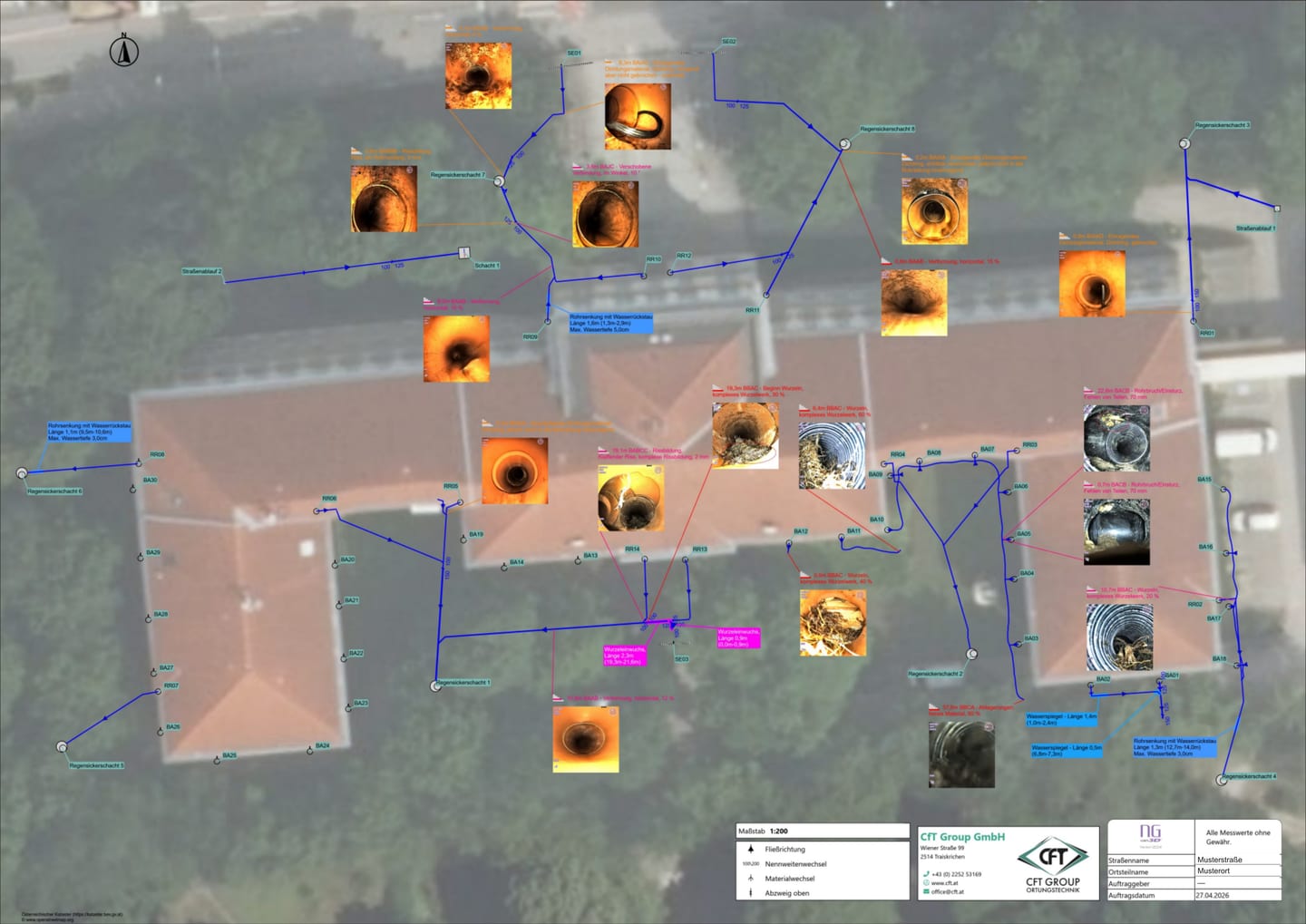
The focus is on the branches: we survey them as far as is technically possible, so that what actually connects to what becomes apparent. Work is carried out from DN 30 to DN 300 – considerably narrower than on section inspection of collecting mains, because the question here is not the collector but what hangs off it. Where a branch ends because the camera head can go no further, that point is marked on the site and recorded as the end of the surveyed section. What is handed over is a plan with the route of the mains and the defects, and a separate report for each pipe and each section; without a GPS survey the plan is a sketch positioned against the orthophoto and not a surveyed plan.
Key facts at a glance
| Methods | Multi-turn steerable camera equipment, digital reconstruction of the pipe network route, sonde location in the camera head, electromagnetic pipe locating |
|---|---|
| Application range | Works networks from DN 30 to DN 300, steerable from DN 100 to DN 200 |
| Duration | Two hours to several days, depending on the number of pipes and laterals |
| Result format | Digital route representation, plan with pipe layout and all defects, a separate report per pipe and section, still images per branch, with GPS a surveyed plan, otherwise a sketch positioned on the orthophoto |
| Service area | Vienna, Lower Austria and Burgenland |
When the as-built plan no longer holds
The typical occasion: a works network has grown over decades, every extension has added branches, documentation was inconsistent. Before renovating, reconnecting or shutting down a section, it must be clear what actually belongs together. The same question arises when taking over properties, when assigning discharge points, and whenever one section is persistently conspicuous and nobody can say what all drains into it.
The 3D branch survey delivers the topology, not just the condition of a single section, and is thus the preliminary stage to the sewer register. With surface marking and, on request, GPS surveying, a permanent positional reference is created on which renovation planning and records management can build.
How the job runs
1. Coordination. We clarify the scope: a single section, a network part or the works network of a whole site. We review as-built plans and older reports in advance; what they contain counts as assumption until the survey.
2. Pre-cleaning. Before the recording we recommend high-pressure cleaning of the sections to be driven. Otherwise the head snags on the first deposit and does not find the branch opening.
3. Survey and route recording. Driving proceeds section by section; at every outlet the head turns in as far as it gets. The distance travelled is assembled meanwhile into the digital route representation. End points and conspicuous spots are pinpointed from above by the sonde; marking is done on the site, on request additionally surveyed with GPS.
4. Handover. Route sketch, still images and inspection report go to you as one set. We walk through the route together. Renovation and reconnection are carried out by the contractor you appoint.
Equipment and methods
Multi-turn steerable camera equipment
What passes by as a dark opening in the pipe wall during a normal survey is, in a works network, often a side run of its own: the drainage of a hall, a yard drain, a decommissioned connection. With a rigid camera head it stays exactly that – an opening in the picture. The multi-turn steerable head turns in and drives on, even across several branches in a row – turning into branches is possible from DN 100 to DN 200, driving from DN 30 to DN 300. If the head gets no further, the point reached is recorded; the section beyond stays in the report as not driven.
Digital reconstruction of the pipe network route
The camera records how far it has driven and with which changes of direction and gradient; from this the route of the network is digitally rebuilt – sections, outlets and side runs in their order and position to each other. For records management the limitation matters: this is a route model, not a survey plan. Coordinates only arise where points are pinpointed by sonde and surveyed with GPS.
Sonde location and electromagnetic pipe locating
Via the sonde in the camera head, the spot where the camera currently stands can be pinpointed from above and marked on the site; so every end point and every conspicuous finding gets a place that can be found again. The route of a whole run is additionally located electromagnetically. On an industrial site, reinforcement and third-party lines lie close together and distort the signal, so every pinpoint is cross-checked before it goes into the documents.
Supplementary methods when the camera cannot get through
A collapsed, built-over or previously severed section cannot be recorded optically – the drive ends before it, and the gap stays in the report as a gap. Whether it can be closed depends on whether a locating method without pipe access comes into question for this section.

What you receive
Handed over is one coherent set: the digital representation of the pipe network route and the still images of the branches driven, plus the position of the markings on the site.
A plan with the pipe layout and all defects. If the pipe run was recorded with GPS, this is a surveyed plan. Otherwise it is a sketch whose position is determined from the orthophoto.
A separate report per pipe and section. So it stays traceable for every section whether it was driven and where it ends – and a contractor can price a renovation offer from it instead of estimating the scope.
We show what we find.
This is how the camera sees a network from the inside – and this is the plan in which every finding sits at its place.
Costs and effort
The effort is determined by the length of the network to be recorded, the number of branches per section, how well the manholes can be reached, the cleaning required, and whether the marked points are additionally surveyed with GPS. Before driving, we name the cost range for the agreed scope.
Frequently asked questions
How does this differ from the CCTV inspection?
The CCTV inspection assesses the condition of a section and codes the defects to the standard. The 3D branch survey does not ask about condition but about the structure itself: how many outlets hang on a section, where they lead and which of them are missing from the as-built plan. A works network usually needs both – first the topology, then the assessment of the sections that are to remain.
How many branches in a row can be driven?
Several in a row; how far it goes shows in the pipe, we do not name a fixed number. If the head gets no further, the point reached becomes the documented end of this limb: noted in the report and marked on the site, so a later job starts exactly there instead of from the beginning.
Down to which pipe sizes does the steerable head go?
Turning into branches is possible from DN 100 to DN 200. Driving goes from DN 30 to DN 300 – outside that range the head still drives but no longer turns into the outlets. That is deliberately the small range: this is about the branches and connections, not the collector. Larger cross-sections are driven by the crawler – that is the CCTV inspection of collector sewers, which reaches up to DN 1200.
Does the route sketch replace the as-built plan?
It shows reliably what belongs together, but it is not surveyed and therefore replaces no as-built plan. Whoever needs positional accuracy for records management has the marked points additionally surveyed with GPS; only then does the recording become a contribution to the sewer register.
Does it have to be cleaned beforehand?
We recommend it. A branch whose opening lies behind a deposit is not found during the drive – and what is not found is missing from the sketch afterwards, without anyone noticing.
Do you renovate the findings right away?
No. We locate, mark and document; the execution lies with the contractor you appoint. Sketch and report are therefore kept detailed – they are the basis on which this contractor works.
Describe the findings.
The more precisely you describe the findings, the more directly we can go to work. Plans, readings and photos help us settle the method in advance.
What happens next
- We read your message and match the case to a method.
- We come back to you – usually with a question that shortens the appointment.
- We confirm the appointment and what it costs before anyone sets off.
Rather talk?
+43 (0) 2252 53169
Mon–Thu 8:00–16:30 · Fri 8:00–12:00
Describe your case.
Fastest by telephone – then we settle straight away which method fits and what you should prepare.
Outside office hours, write to office@cft.at.